Thread #2969431 | Image & Video Expansion | Click to Play

My Advanced Realistic Humanoid Robots Project - #7 Artbyrobot 01/06/26(Tue)21:07:10 No.2969431 [Reply]▶
File: abel.jpg (387.5 KB)

387.5 KB JPG
Last Threads: https://warosu.org/diy/?task=search2&search_username=artbyrobot
To begin: the project goal: I am working to make a series of humanoid robots. I am using a Biblical theme of naming the first 3 robots I make Adam, Eve, and Abel. The goal is for these robots to have human body inspired musculoskeletal systems, advanced AI, and that they look human and pass for human to a casual observer at least at a distance. They must be able to walk, talk, run, dance, do sports, do chores, manufacture products, and make more robots just like themselves if not even better. My aim is to build a single robot arm and head and then add sufficiently advanced AI to that arm and head to enable it to build the rest of its own body for me. This way I am delegating the work of building the majority of my first humanoid robot to that robot rather than doing that work myself - and this is to save me time.
In a like manner, my goal with the AI is to code just enough AI that the AI can begin coding itself and this way I don't have to code most of the AI myself because it will self create itself. I liken this to building a seed and that seed growing into a tree because for me to code that tree would take too long for me and just creating the seed would then save me time.
60 RepliesView Thread
 Showing all 60 replies.
>>
>>
>>2969436
Terry was just a wacky believer and assumed role of a priest. Larry has a clear God complex
>I am using a Biblical theme of naming the first 3 robots I make Adam, Eve, and Abel
Like, that's just attempting to mimic God, but he's obviously far away from godhood, since God created Earth and people in 6 days while after 11 years, Larry stuck at constructing antennas from copper wicks and discovering copper tape on ebay
>>
>>
>>2969714
My decision to use Biblical names of first humans was intended to b a homage to God, reflect my love for the God's Word, and was done with the intention of all humility toward God. My robots are being built with respect toward what God made and have grown my respect toward God as a superior designer. Art mimics life and God created all life. So art mimics the creations of God generally. It should be done with reverence toward God which is my intention. I do not want to usurp God in any way, only pay homage to Him.
>on project for a long time
Not really I've taken long breaks constantly and repeatedly only working in short spurts here and there. If someone in 1k years spent 5 minutes on a project that doesn't mean they work slow it means they did not work on that project much.
>>
>>2969850
>My robots are being built with respect toward what God made and have grown my respect toward God as a superior designer.
You're claiming you understand God better as a "superior designer" because you made up (never built) some robots lmao, obviously you're comparing yourself to God and thinking there's some kind of analogy. Christianity has like 2000 years and during that timespan noone has decided to "honor" God by creating another humanoid creature - you know what it'd be called normally? Playing God. Thing you're paying homage to is a jewish myth of Golem.
>I do not want to usurp God in any way
You don't "not want", you can't.
>If someone in 1k years spent 5 minutes on a project that doesn't mean they work slow it means they did not work on that project much.
You're pouring as much attention and time into this project as you can, but you're just too slow. Everyone has to take breaks, people work 8-12 hour shifts and go take a fucking break at their homes. Construction, software development, etc. - it all can take months and years precisely because people take breaks and have days off. Nonetheless, they do their work more efficiently and faster. You're not in a special set of circumstances, you're just outstandingly incompetent and too sensitive. I think you're actually closer to offending God with your sloppy work than honoring Him.
>>
File: 35570000062_a6731a1c58_z.jpg (40.9 KB)

40.9 KB JPG
>>2969850
>yea I have this grandiose, revolutionary, world-shattering concept I work on to honor God almighty himself. I just don't feel like spending too much time on it.
>>
>>2969955
>people in their jobs take breaks just like you do
no, they take a day off here or there. I have taken multiple consecutive years off multiple times. Not the same. They are full-time working on a single project with all of their focus 40-60 hours per week. I on a good week am doing like 4 hours that week. No the same. Someone achieving more in 60 hours than someone did in 4 hours does not mean they are more efficient or a faster worker.
>you are comparing yourself to God
yes I am weak and he is strong. That's a comparison. That's a humble position, not a brag.
>you saw God is superior to you as a designer by working on your robot project
correct. I supposed why not have a nose bone? I thought I'll use a bone there. Then I later realized if the robot face planted that bone would get shoved into the skull, penetrating anything therein and would have converted into a weapon of destruction. So a bone cannot be there but cartilage can. So the thing forming the nose shape must be cartilage like, not bone like. I learned WHY the nose has a cartilage-like design, not understanding it or considering it until I questioned it and thought I'd change it. In my attempt to improve the design or modify it I discovered the reason for the original design and was able to marvel at the brilliance of it. Giving glory to God for it. And so it has gone for many studies regarding it and there are other examples like this. So yes, whether making a robot involving studying the body's design or studying it for medical school purposes or w/e you come to appreciate many parts of its design and if you believe in God as creator then you naturally marvel at the work of His hands and the cleverness of his designs.
>>
>>2969994
>I find I can honor God through my robot project but don't like spending too much time on it
Nobody said I don't LIKE to spend too much time on it. That's not true. I just have other pressing matters to attend to on a regular basis. And you also suppose that this project is the ONLY way I can honor God which is also not true. I can honor God in countless other ways and do so. So honoring God less often in one way I honor Him does not diminish my overall honoring Him as long as the other thing I do when not honoring Him with this project honors Him equally. As long as one is acknowledging God in all their ways they are honoring him always. As long as one prays unceasingly they are honoring him always. As long as one is obeying God always according to their knowledge they honor him always. One does not need to find a single way they can honor God and then just do that thing on a near constant basis as you falsely suppose. That would lead to terrible work like balanced and being neglectful of your other responsibilities and so very foolish indeed.
>>
>>
>>2970001
>I on a good week am doing like 4 hours that week
If you think you're going to build a robot that builds itself and design AI that upgrades itself by working on those 4 hours a week then you're either retarded or delusional. You can't honestly both claim that you're going to complete this project and excuse yourself with having other shit to do
>Someone achieving more in 60 hours than someone did in 4 hours does not mean they are more efficient or a faster worker.
bro, you're buying random shit off amazon and trying to use it in your project, documenting failure after failure. You're obviously inefficient, unskilled, untrained and incompetent, keeping yourself in the comfort zone by fetching answers along the way from a chatbot.
>yes I am weak and he is strong. That's a comparison. That's a humble position, not a brag.
You literally implied you learned to appreceate God more as a creator because on your "work" on a humanoid robot. What a way to show your humility lmao. You clearly have God complex, you're unable to admit your delusions or your faults, and most likely you're driven to build these robots because of your compulsive need to control other beings, whilst being too repulsive to most of actual people.
>>you saw God is superior to you as a designer by working on your robot project
I didn't even claim that, it's fascinating how 80% of your reply is reply to your own argument that you made up. You're going to go to hell for being prideful alone, forget wanting to fuck the robot.
>>
>>2970004
okay give me an example of your on regular basis pressing matter that takes precedence over building a world class perfect humanoid robot with human-like mind that all armies in the world and private sector would kill for.
>>
I was randomly talking to chatgpt about how I have been feeling burdened by having to make my own BLDC motor controllers for my robot lately and it randomly mentioned integrated half-bridge power modules as something I could use to cut down on my labor load in making these motor controllers. This immediately stood out to me as something I'd never heard of and something intriguing. I have so far been working on my lowside switch and highside switch which together form a half bridge. Many solder connections have been involved and alot of discrete components are involved. The concept of an integrated half bridge on a single chip - meaning two big power mosfets and all the drive circuitry for those power mosfets all condensed into a single chip would be a huge reduction in size and component count as well. So I researched if any are able to do 8v 30a for my 2430 BLDC motor's needs. Turns out there are some out there. At first I was looking at Texas Instruments CSD95377Q4M Half‑Bridge Driver (30A) which can do 30a continuous so perfect for me. However, I didn't want to lock myself into a single vendor chip that may one day be discontinued. I prefer something ubiquitous with many competitors making it that can be purchased from aliexpress. Something commodity level. This way I future proof it and don't have to worry about any one manufacturer discontinuing parts I'm using and prices soaring because of that or simply the part becoming unavailable. So after a bit further digging I found CSD95481RWJ QFN chipset on aliexpress sold by several vendors and one was under $1 each. So it is equivalent to two power mosfets plus all drive circuitry for each power mosfet all for under $1.
>>
File: H-Bridge-IC-Chip-CSD95481RWJ-QFN-Chipset.jpg (96.1 KB)

96.1 KB JPG
This one also has 60a continuous rating. It is only 5mm x 6mm in size which to me is insane. This is so much smaller than the setup I've been working on yet just as powerful. They are usually used for tiny buck converters and used directly on videocard PCBs and in servers and in automotive PCBs and much more. In any case, using 3 of these half bridge chips you can drive a BLDC motor. The consolidation of so many parts into such a tiny package is truly blowing my mind. So I ordered 60 of these chips - enough to drive 20 BLDC motors. I am leaning toward using these for all my motor controllers if working with them is easier than working with discrete components like I have been. They are cheaper to work with I think - I'd have to run the numbers on that though. They even have built in temp sensing we can read in which is a bonus. Their built in current sensing will not work for BLDC motors so I'll still need my shunt resistor current sensing circuit setup external to it but that's ok. All in all these appear to be a game changer in terms of reducing part count so less potential points of failure and also reducing board footprint so miniaturizing my electronics even more which is very good for us. I'm still needing to work out now how I want to hook these up in terms of PCB making for it and any discrete external components needed to support it. It is also top cooled which is interesting. I'm envisioning using silicone thermal adhesive to glue on a copper pad that has my braided solder wick wires already soldered to it. These will carry the heat away to my water cooled pipe system.
>>
I'm kind of amazed that nobody really seems to use these for BLDC motor controllers. They seem perfect for it. Maybe I'll start a trend. Assuming I don't find out the hard way why they are never used for this application!
note: the full product title: "(5pcs)100% original New CSD95481RWJ 95481RWJ CSD59950RWJ 59950RWJ QFN Chipset"
note: for my previous BLDC motor controller design I was needing to use 6 digital IO pins to drive a single BLDC motor controller's 6 power mosfets by way of their control circuitry. But for a BLDC motor controller design using 3 CSD95481RWJ H-bridge chips, I will only need to use 3 digital IO pins on the microcontroller. These CSD95481RWJ H-bridge chips use a pwm pin that is a tri-state pin - you can have high, low, and floating as the signal you send to it from your microcontroller. Digital output high and low are the usual digital output modes but the floating mode you do in your code by configuring the pin to be a digital input pin which makes it a floating pin. These 3 states fed into the chip makes it either give you V+ as its output or V- as its output or just off/floating as its output. This corresponds perfectly to the normal h-bridge 3 states we'd be using with our discrete components previous microcontroller design. So this savings in total digital I/O pin usage on the microcontroller means you can drive more motors per microcontroller in theory which is pretty cool.
>>
>>
Well I deep dove into the CSD95481RWJ IC route. I estimate it will cut the work in half roughly for every motor controller made and cut the size taken up by about 60% compared to my previous discrete components approach.
Now I will note that I did come across the BTN8982TA which is rated to 40v and can handle 30a continuous 50a peak short burst. But it's TO-263 form factor so about 4 times as big as the CSD95481RWJ. It also costs about $2 each so double the price. It's not a bad option though all things considered but just not quite as good as the CSD95481RWJ for the reasons mentioned. I note it here so I don't forget about it. It can be a great option if the CSD95481RWJ doesn't work out in the end or something.
Anyways, for the thermal concern - which is my biggest concern, I plan to top cool the CSD95481RWJ using a .2mm plate thermal siliconed into place on top of the CSD95481RWJ and then solder a bundle of 4 braided solder wick wires to that and run that off to the water cooled copper pipe about 4" away. The top cooling only handles about 30% of the cooling according to chatgpt. The most important 70% is from the bottom cooling through its pads on its bottom. For this I plan to use double stacked .2mm thick copper plate soldered to its IC pads. So that's .4mm thick. Also it will be around 2mm wide where it attaches to the pads. It will then route out from under the chip and swing upward into free space and head over to the 8v+ and 8v- buses coming from the 8v motor battery banks in the robot's lower torso. These thick copper traces I will fork off of with braided solder wick wire right near the CSD95481RWJ IC chip for thermal conductivity reasons. This braided solder wick wire will be live so I will wrap it in fiberglass window screen so nothing can touch it - preventing short circuits. It will then be electrically isolated from where it connects to the water cooled copper pipe with thermal conductive tape.
>>
The braided solder wick wire attaching to these thick copper traces will be a bundle of 4 per trace. The various decoupling capacitors this chip calls for I will connect to its output pins using flat flex PCB DIY hand made. I'll be attaching this PCB first and attaching the thick copper traces to the underside pads second as a separate layer that goes underneath the flat flex PCB layer. The flat flex PCB layer will mostly stay around the outsides of the chip and have its center cut out and removed - the part of it that would get in the way of the underside main pads under the chip. So the flat flex PCB will just hug the outsides of the IC mainly in a U shape around the chip leaving the center of the bottom of the chip free to solder to with my thick copper traces.
Note: the thick copper traces will be cut out with scissors from a roll of .2mm copper sheeting I bought on amazon which I mentioned a few posts back. Double stacking it wil double its thickness and increase its conductivity both electrically and thermally.
>>
File: half-bridge-ic-schematic.jpg (380 KB)
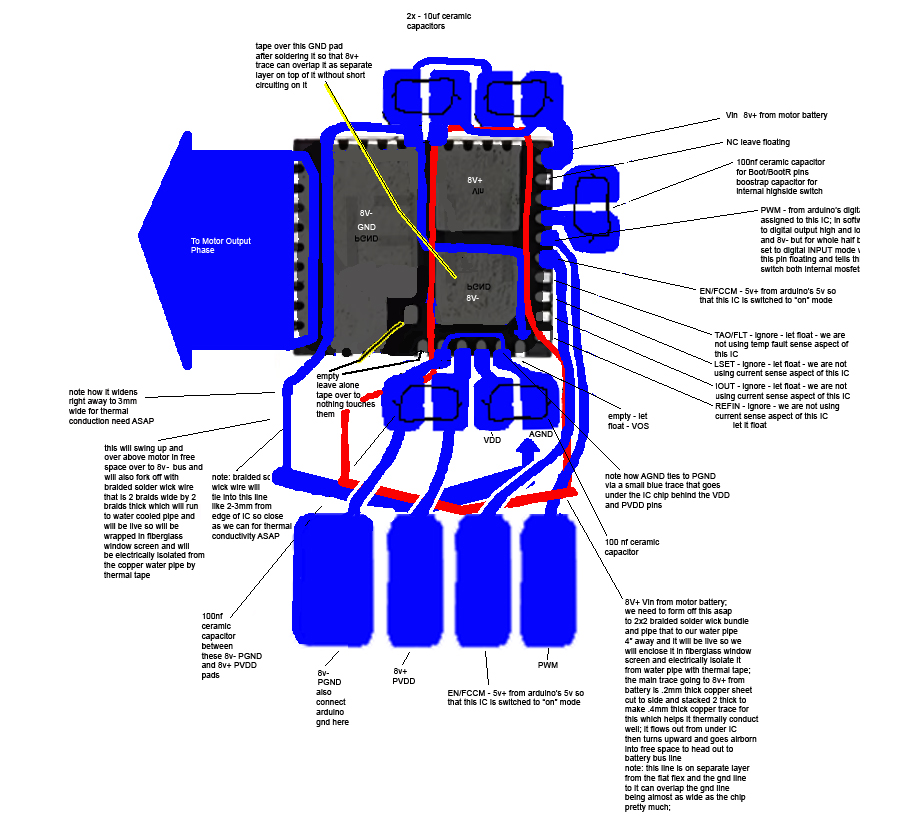
380 KB JPG
Note: in a usual setup with this CSD95481RWJ IC, a multilayer board with a array of vias is used to bring the heat downward off the chip and into another lower layer within the multilayer board where it can then radiate on said layer outward in every direction. In my approach, I use thicker traces than the layers of a multilayer PCB has so I have alot more local copper in play. Then instead of the heat transferring down and then outward in all directions on very thin copper, mine travels down then in a single direction outward away from the IC on that trace. The trace will need to be as wide as possible as soon as possible. I expect to get it from 2mm width - the width of the pad - to 5mm width within a few mm. This rapid transition to a wider width combined with the use of much thicker copper compared to a multilayer PCB's copper thickness of its layers means I should be able to exceed the thermal performance of a multilayer board using my approach. Especially since I also plan to quickly fork off the main traces with bundles of 4 solder wick wire braids that will carry the heat off to a water cooled pipe 4" away.
Note: in my attached schematic I only show a single CSD95481RWJ IC because they are all wired up the exact same way. It's just doing it 3 times for each of the 3 phase wires of the BLDC motor.
Note: I will use a single electrolytic capacitor per motor controller also not pictured in the schematic.
>>
>>
>>
BLDC Driver ICs exist you know. Go on the Texas Instruments website and look for them, there are many options available. In a project like yours, you should probably use ready-made solutions whenever possible so there's less stuff you have to worry about.
>>
>>
>>
>>2971648
assuming you and this >>2971501 are both going the sexbot angle, that is not the intention of this thread/project. I've been very clear on this anti-sexbot stance from the beginning. I am opposed to sexbots period. I am not building one. Not sure why people jump to that conclusion, nothing I stated about the robot says anything lending to that assumption.
Also consider this: if you create advanced AI that goes around telling married men to come lay with it, then you are creating a whorebot essentially that is morally deficient and at the very least simulating adultery. Adulteressbot. No, my bots will be morally upright and Bible thumper bots.
>>
>>
>>2971736
I agree its not literal adultery which is why I said it is simulating adultery. Jesus said if you even look at a woman to lust you have already committed adultery with her in your heart. So if looking the wrong way God considers a crime, then simulating adultery in other ways than mere heart imaginations surely is in crime territory too wouldn't it seem?
>>
I urge you to tread carefully, for what you are doing is not without profound ethical and spiritual implications. Remember the words of Ecclesiastes 7:13-14: "Consider the work of God: for who can make that straight, which he hath made crooked?" It is essential to reflect on the divine order and the sanctity of life as you work on this project. If you are a man of faith is it really worth an eternity in hell to create a sexbot?!
>>
>>
>>
File: ndbs22bhgjb91.png (22.4 KB)

22.4 KB PNG
>>2971716
Hedonismbot disapproves
>>
OK, so when I was thinking of using both my discrete components motor controller design parts I already made and then also separately implementing the integrated half bridge IC design going forward, it hit me that the 8v- and arduino gnd tie together on the half bridge IC by necessity but this ruined their intended isolation I needed for my discrete components motor controller design particularly for the lowside switching portion of that schematic. On the lowside switching portion, the little mosfet has 12v- and arduino gnd tied to its source pin. If on the integrated half bridge I also have to tie arduino gnd and 8v-, then that means 12v- and 8v- and arduino gnd are all tied together always.
That completely ruined the necessary isolation between arduino gnd/12v- and 8v- that I had intended to be in place for my lowside switch setup. So that was bug #1 freshly introduced that I would then need to solve for in my discrete components motor controller design. When studying this out on the discrete components motor controller design, another error hit me: when any lowside switch turned on in the design, the 12v- dedicated power supply gnd and the 8v- motor supply gnd become connected as long as that lowside switch is on. Since every lowside switch had always access to 8v gnd on its source pin, then even one moment of 12v gnd and 8v gnd attachment anywhere on the robot would cause every lowside switch in the entire robot to immediately turn on at the same time.
>>
So if any turned on, then all turned on. This was a huge oversight. For some reason since I only designed and focused on one half bridge conceptually at a time, I did not consider the effects one half bridge has on its neighboring half bridges. This just never occurred to me. I guess conceptually I envisioned that every half bridge had its own personal 12v ground from its own personal 12v supply that was electrically isolated from the entire rest of the robot. But of course that's not practical even if it is technically possible. So in testing, things did work, but would have failed as soon as I tried to test more than one half bridge at a time. So I caught this bug before testing revealed it.
I discussed this horrible situation with chatgpt and it taught me that in a complex system like a robot, grounds of all your different supply rail voltages cannot be relied on to be isolated from one another like I was treating it. Even if at times they were momentarily, one switch, one change and suddenly they are not and it all becomes a common system ground again. So if I can't safely assume a ground for any given voltage is safely disconnected from the grounds of other voltages, I should not rely on switching on and off access to any particular ground to any of my lowside switches. Instead, I should be shorting the gate driver of the lowside switches to ground to shut them off rather than messing with their source pin's ground connections like I was before. I am to leave the source pin's ground connection as 12v- and its gate connection as 12v+ at all times except when I want to shut it off - at which point I short the gate pin to gnd using my logic level mosfet to do so.
>>

The fix was very straightforward and minor: I just had to add a 100ohm resistor in series with the gate pin of my big power mosfet lowside switch and then reroute my little mosfet a09t drain pin to the big lowside mosfet's gate pin instead of its source pin. The connection to its gate pin must be downstream of that 100 ohm series resistor so that the path from the big mosfet's gate pin has almost zero resistance when traveling through the little mosfet's drain line and over to its source line into ground. This way when you turn on the little mosfet, the big mosfet's internal capacitor quickly empties out, flushing into the path to ground created by the little mosfet and that discharges the big mosfet, shutting it off. When you want it back on, you shut the little mosfet off, which allows the big mosfet's internal capacitor to charge up again, which turns the big mosfet back on. So the setup now acts like a normally on relay.
Note: the resistor on the drain line of the little mosfet that we used to have when it fed into the source line previously is now removed. We want no resistance on there because that would impede the little mosfet's ability to discharge the big mosfet's internal capacitor in a timely manner. We want to be able to not only discharge that capacitor quickly but also direct all incoming current from the 12v+ line that makes it past the 100ohm resistor heading for that big mosfet's gate into our ground path. This rapid redirect flushes so much of that already limited current that hardly any can make it inside the gate of the big mosfet which causes the gate of the big mosfet's voltage to approach near zero volts. So it's called a "pull down" path to ground.
Attached is a photo of my schematic before and after the fix.
>>
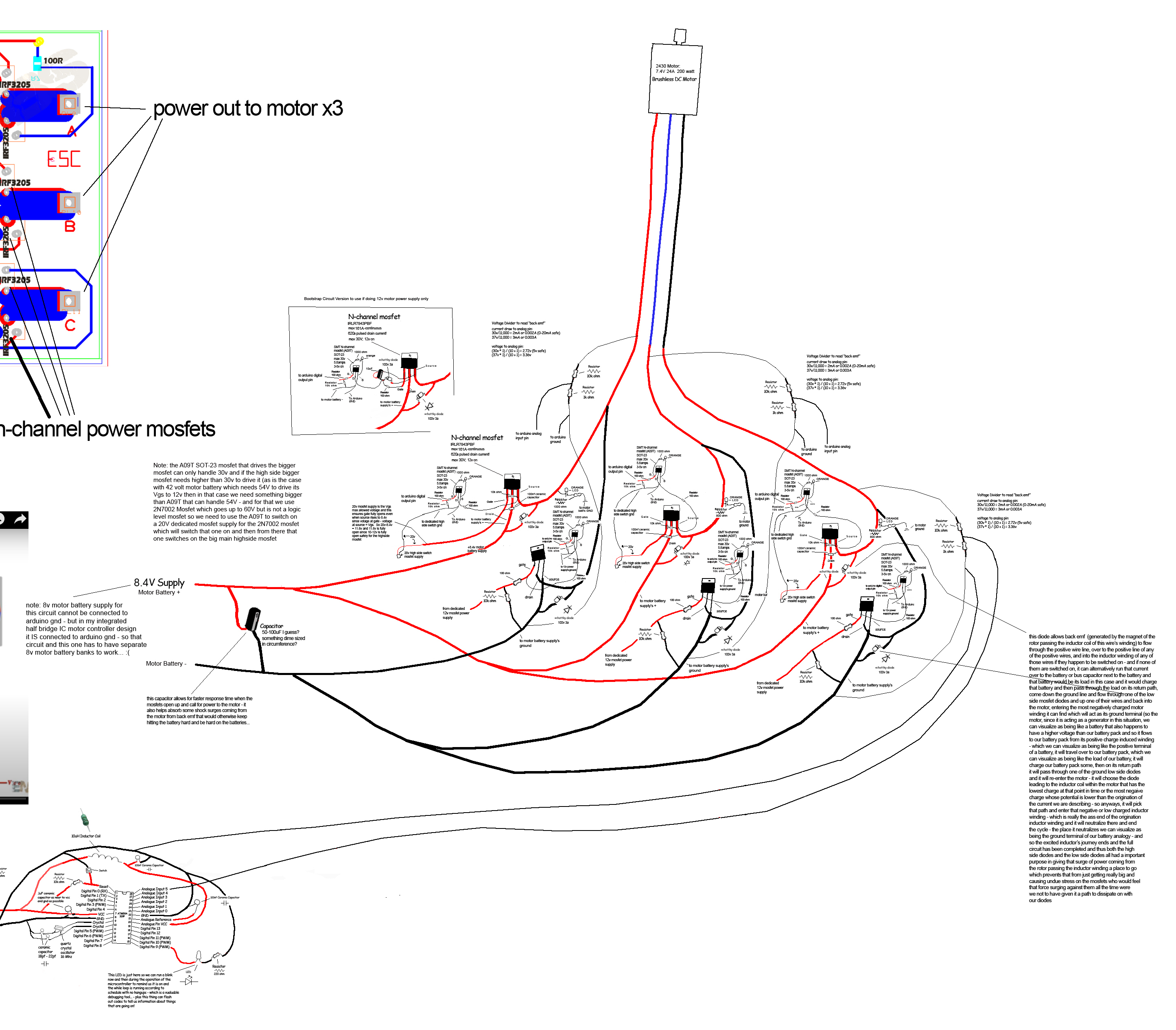
Attached is a photo of full updated schematic with the changes in place.
That all having been said, this discrete components original bldc motor controller design, now fixed, is worth keeping archived, but is now basically abandoned now that I have access to the time, money, and space saving shortcut of my integrated half bridge IC based design. It's kind of sad to abandon something I spent so much time on, but who knows, I may still use it if I ever come across a motor that I can't find a cheap half bridge integrated IC for in the future. It's a great schematic to have at the ready for that scenario.
>>
File: in-series-style-bldc-motor-controller-phase.jpg (429.3 KB)

429.3 KB JPG
Ok so I was thinking now that each half bridge is just a tiny IC rather than a pair of hefty power mosfets, the space taken up overall by my entire bldc motor controller is going to be about 3cm x 1cm x 2mm which is insanely small for 30a continuous at 8v motor controller! This realization caused me to reconsider whether I even need to treat this as a single motor controller cluster that has to be sat like a horse saddle onto the side of my bldc motor - my original intention for my discrete components original design for my original bldc motor controller. What I realized instead is that things are now so small that I can simply build a half bridge for each phase as a inline element nested inside the cable run leading to each phase wire of the bldc motor. So instead of having a dedicated spot for each motor controller, I'm going to have just a slight bulge in the phase wire leading out from the bldc motor and that bulge will contain the half bridge that handles that phase wire. All nested inline. This is the easiest way to implement and most streamlined I think. It also means the whole motor controller will just be "floating" in midair, not actually mounted to any motor or anything at all. Just part of the wire harness nested right in there. This is a radical approach IMO. Only made reasonable by the fact we miniaturized the design by such an insane degree.
So the previous version of the schematic was intended to be mounted to the side of the motor like a horse saddle and had an l shape so inputs would come up from bottom and outputs out to left side toward motor phase wires. These L shaped half bridge setups would be stacked next to eachother side by side. In the new variation everything is inline, inputs coming from right and outputs exit out left side to motor.
Here's the updated inline variation of the schematic (no longer L shaped flow like before).
>>
>>2971964
>>2971965
>>2971966
>>2971967
>>2972075
You should get this working on a breadboard first.
It might be difficult with quite a bit of trial and error to get the arduino giving the right outputs at the right times to drive your motor.
Having to probe a bunch of components that are hanging in the middle of a cable sounds like a giant pain in the ass. Your probe clip will be dangling from component leads, putting strain on the solder joints or potentially shorting things together. If you use a probe without a hat or clip, the board will be pushed away from you and moved around when you go to measure stuff.
Also, as your robot moves around these drivers might end up banging into each other and other electronics shit inside. You have a very high density of motors
>>
>>2972087
>use breadboard first
this ic is so tiny it can comfortably fit on my pinky fingernail. so i have to make a flex pcb to even interface with it. breadboarding works if you have breakout headers you can plug jumper wires into. It isn't a timesaver for this
>difficult timings
not really. there's just 3 phase you can walk through them at any speed. I'll just trial and error till it creates pseudo sine wave though.
>probing in middle of cable a pain
I don't think so. I just pinch probe tip against it with fingers or w/e to hold in place for something like this. I don't use a probe clip.
>drivers might be banging
well sure but I don't think that should be a issue and should not happen that often the wire won't be that floppy it should just wave in the air like electrical lines overhead blowing in the wind. I also might wrap the whole thing in rubber to protect it. It will be pretty robust I think.
>>
>>
>>
>>
>>2972715
I drew the schematic in photoshop with pencil tool and that same schematic I plan to print onto transfer paper and laminate onto copper and etch the copper board to make the circuit from that drawing then. So the drawing is not a waste of time it is literally the first step of a diy circuit for the motor controller. It's not a wasted step or an extra step or a skippable step. It's needed 100% so zero waste of time at all.
>>
File: updated-CSD59950RWJ-integrated-half-bridge-schematic.jpg (469.9 KB)
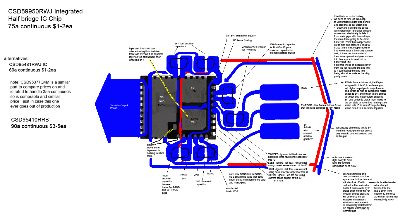
469.9 KB JPG
Ok so I realized I don't have to feed in 8v+ from an external wire when I can just pull it from a neighboring pin on the chip that has 8v+ already fed to it from one of the big 8v+ copper traces attached to one of the big 8v+ pads on the underside that connect directly to one of the side pins. That side pin can then be routed to any 8v+ requiring pins if I can find a path for this routing - which I did find. So that is one less external wire input needed - bringing total external input wires needed to 3 instead of 4 as far as the 30ga wires I need to attach. So now all I need for 30ga wire attachments are 5v+ from arduino, GND from arduino, and PWM from arduino. This saves work and simplifies the wiring so its a great improvement.
Oh and I also did the same thing for the 8v- feed, pulling it from a local pad rather than a external wire feed for that.
>>

>>2972920
Also, I have separated out the PCB traces themselves and made them black instead of blue for printing them onto the PCB transfer paper and laminating this onto the blank Pyralux flex PCBs for etching them. I also mirrored it since it prints and laminates backwards onto the PCB.
>>
>>
>>
>>
sup, I'm the robotics PhD guy from a few threads ago, can you tldr me on the progress ? Last time I told you to test one joint, did you achieve that ? Also is your mental health better? I remember last time you seemed completely narcissistic and delusional about your work, did you reconsider some things?
>>
>>2973334
also as a cool little trick that could save you and the other retards over at /robo/ a fuckton of time. There's something called motion diffusers (you can find a well structured GitHub), you can map the results of the motion diffusion to whatever your upper body kinematic model is to have a robot able to move based on a text sequence. I've been able to test this in my lab on a simple humanoid and using this method you don't need any training or anything. I remember you were hostile to having deep NN and had delusions about being able to make the robot work with a rule based algo, you could use this type of high level rules / sentences as inputs to what I just said.
>>
>>2973334
>can you tldr me on the progress
there was none
>did you achieve that
no
>>2973337
>There's something called motion diffusers (you can find a well structured GitHub)
Larry will not waste his time on learning all that stuff, he's cutting corners by drawing his circuitry in ms paint, instead of using CAD, how could you possibly expect him to delve into github scripts
>>
>>
>>2973577
A little bit more calibrating the test prints of the circuit and verifying its perfect then doing the whole diy pcb process then soldering on the tiny IC and its supporting caps/resistors etc then attaching all the wiring to that and testing it then repeat that 3 times to get all 3 half bridges and then I can test the motor and code the motor firmware.
>>
>>
>>2973679
in my trace alignment I was having to do pixel level modifications and reprints to verify the pcb traces/pads perfectly match up to the pins on the chip. that part has to be perfect. imperfections in the toner transfer, mixing ratios of etchant, copper prep etc cause the trace imperfections you are referring to and that's process related and not at issue as long as everything has continuity and will naturally improve with iterations as I dial in the process with each attempt.
>>
>>2973731
>in my trace alignment I was having to do pixel level modifications and reprints to verify the pcb traces/pads perfectly match up to the pins on the chip
How can you do this and at the same time claim that you're saving time by not learning kicad
>>
>>2973772
it still is less time IMO but the gap is closing on this IC specifically because the margin for error got ridiculously low due to the 0.4mm pin spacing its insane. The other circuits were a clear major timesave but this is another level. However still a time saver nonetheless.
>>
>>
>>
File: 1000005819.png (270.5 KB)

270.5 KB PNG
>>2973406
And here I was, thinking this guy was not super smart for using a pulley system, forced to admit that was the least stupid design decision he made. Seriously, not taking 3 days to learn kicad and order your PCB online but doing it on MS fucking PAINT is just incredible, topkek. Godspeed Arty, just as a heads up we have 2 master and 1 undergraduate students that were able to design build and train 3 humanoid robots in the same amount of time it took you to (not) do a PCB design for BLDC motors. But beyond making fun of you, I really really recommend you to stop being retarded and test your components separately, buy a BLDC driver and test your arm joint (as I said last year) and realise how bad your design is. Don't wait to assemble everything and then realise that every single part of your design is dogshit. I want to start making threads about my papers to mog you but I was wondering how could I do that without doxing myself
>>
>>2969431
I'm not a hater or anything, but I have to warn you Arty. Last night I was visited by an angel in my sleep. He told me God is mocking you by giving you tasks you can't accomplish. He's making a fool out of you to make an example. He called your project "Adam 2 electric boogaloo", mockingly.
>>
>>2973781
Tinkercad's good for making schematics out of circuits on breadboards or with point-to-point connections, but its library of components is a bit limited (it doesn't even have thyristors or accelerometers, for instance), so I probably wouldn't use it for anything too complex.
I guess it's fine for a first course on electronics taught at a community college, but probably not for high-complexity projects like what OP's trying to make.
My personal choices for schematics are Microsoft Visio and LibreOffice Draw, mostly because they're much cheaper than AutoCAD or any other professional Autodesk product.
KiCAD? It's good for PCBs that need to be made in large quantities, but it's not what I would use to make an electrical diagram of something like an HVAC system or an industrial control panel.
Then again, for OP's purpose, which is to lay out the actual traces of a circuit board and specify the exact placement of each component, with footprint specified and all, an EDA program like KiCAD or EasyEDA is exactly the solution needed for his problem. He could even supplement it with the StepUp plugin for FreeCAD if he wanted to design PCBs with special mechanical characteristics (i.e. flex PCBs or PCBs with an irregular outline)
Then again, every man is free to spend his spare time as he will.